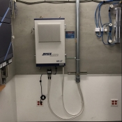
Quad Band Digital Repeater (27dBm)
Quad Band Digital Repeater (27dBm)
With Dynamic Filtering & Remote Access
Product Overview
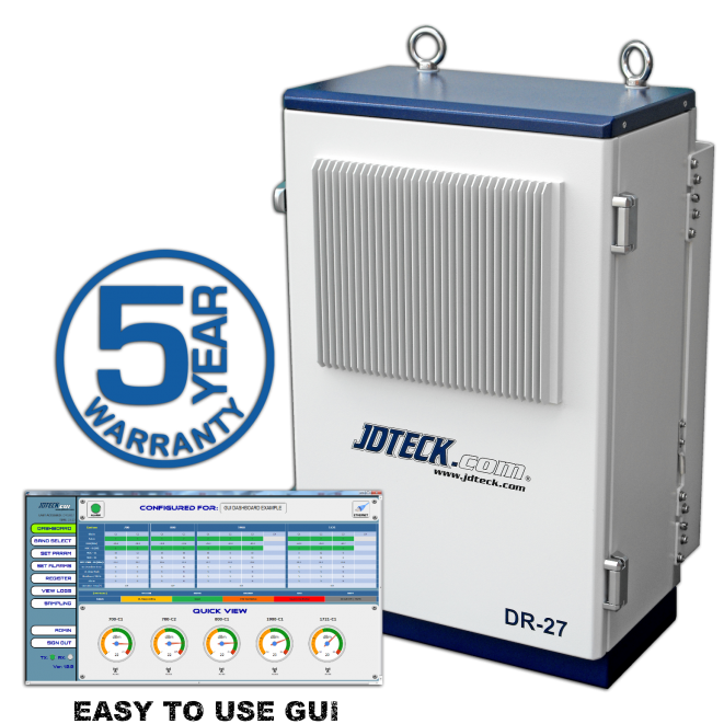
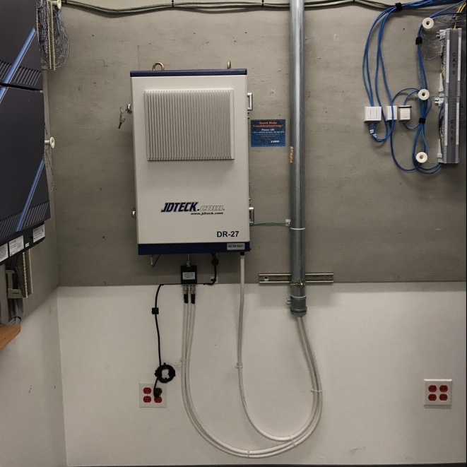
JDTECK's all-in one Quad Band Digital Repeater can operate in either a pre-set channelized mode, wide-band mode or custom-band mode with just the click of a mouse. This high-powered, gain adjustable, quad band digital repeater is perfect for use in a DAS needing to provide enhanced coverage for all the major Wireless Service Providers (WSP's) simultaneously while yet being able to individually adjust each carrier's gain and output power level.
Using a Small Cell as your signal input source for one WSP while another provider's source feed might be OTA (Over The Air) is easy to configure with this advanced digital repeater from JDTECK. Deploying a DAS in a dense metro environment where one WSP's tower is right across the street thus over-powering some of your inputs, while another provider's signal is coming in very weak is exactly what this unit is capable of balancing out . With up to 40 dB of on-board manual attenuation in the GUI itself, plus an additional 10 dB of Automatic Gain Control (AGC), fine tuning and balancing all your outputs for each carrier is very quick, easy and accurate. Our repeaters are built with carrier level optimization in mind. Therefore, only the highest quality components are used which maintains very good RSRQ, RSRP and SINR values throughout the DAS.
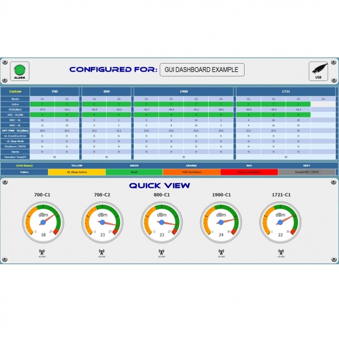
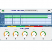
The highly intuitive Graphic User Interface (GUI) allows the user to select the desired active bands or channels they want to amplify, turn down or even turn off the bands they do not want to pass (Uplink & Downlink) all with the click of a mouse. Easily set any alarm trigger point as well as configure and control any parameter of the repeater. Need to narrow the active blocks by just 1 or 2 megahertz to avoid adjacent channel interference? That's no problem with the Quad Band DR Series from JDTECK. This can be done either locally or remotely via Ethernet or USB using any PC or mobile device. It is hands down the most intuitive and user friendly GUI designed to date.
An Air Sampling feature has been incorporated into the GUI which allows the user to sample the inputs of all the bands and carriers so the appropriate level of attenuation can be added in the GUI even before live transmission. This helps to reduce any macro interference events at commissioning. This feature also doubles as an on-board 'spectrum analyzer' letting the user know all the active inputs the donor antenna is receiving.
On our Gen 2 version, easily setup your own custom trigger points and receive automated alarm notifications via email which supports both IPv4 and IPv6 protocols with encrypted https communication (or SMS with optional modem) for a host of metrics including: Low RSSI Limits; Low Output Power Limits | MUTE Shutdown Activated | Signal Oscillation Occurred |Temperature of a Specific Band is Over Limit | One of the Authorized Account Users has Accessed the Repeater (Up to 5 users) | Repeater has Lost AC Power | (On-Board Backup Power for up to 15 mins for management system using Super Capacitors!).
The really neat thing about this product is the ability for the senior RF engineer on staff to be able to remote into the repeater, commission and optimize the DAS from anywhere there is internet. The integration team completes the deployment and with a mobile hot-spot (or if allowed on the customer's guest network) provide a web connection to the repeater so the highly skilled RF engineer who is an expert at optimization can finely tune the DAS without needing to be physically on site. This process is typically completed in 15 mins. The integration / installation team is then able to walk the entire space to complete benchmark testing, verification and acceptance by the customer.
Each repeater is programmed and bench tested before it ships, which includes a certified test report, so you are assured of strict quality controls and NO dead on arrivals.
|
|
SKU:
This highly advanced digital unit uses a Graphic User Interface (GUI) to access and select the desired active bands or channels, set any alarm trigger points as well as configure and control the parameters of the repeater which by extension controls the entire DAS it’s mated to either locally via USB or remotely via Ethernet.
To maintain safe and specific output power levels, the GUI of this industrial grade digital repeater has a wide range of configurable settings which allows the repeater to function strictly within the parameters set by the end user. These features include built-in Signal Oscillation Detection circuits with color changing indicators for the respective bands (Green, Orange or Red depending on the intensity), Automatic Gain Control (AGC) which will dynamically reduce the gain of the repeater up to 10dB if oscillation or a high input signal is detected. Manual Gain Control (MGC) to bring the repeater into a set safe operating limit as well as a Network Safe / Auto MUTE feature that immediately shuts-down the RF transmission circuit of any frequency band that exceeds its set output power limits. There is also an Uplink Sleep Mode which shuts down the UL band of the repeater if no activity is detected on the DAS after a set period of time. All features that rigorously protect the macro cellular network from harmful interference.
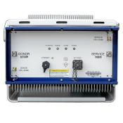
There is master alarm indicator on the header of the GUI as well as an external LED on the enclosure of the repeater which changes color from green to red to alert the user if any alarm is detected. The user also has the option to have the repeater send automatic email or SMS notifications to specific addresses or numbers alerting the recipients to access the repeater to make any needed adjustments.
Frequency Chart
| Model | Uplink | Downlink |
|||||
|---|---|---|---|---|---|---|---|
| JDIR-LCPA-DR27 | 700 MHz | 18 MHz | 698 ~ 716 MHz | 728 ~ 746 MHz | |||
| 11 MHz | 776 ~ 787 MHz | 746 ~ 757 MHz | |||||
| 800 MHz | 25 MHz | 824 ~ 849 MHz | 869 ~ 894 MHz | ||||
| 1900 MHz | 65 MHz | 1850 ~ 1915 MHz | 1930 ~ 1995 MHz | ||||
| 1721 MHz | 45 MHz | 1710 ~ 1755 MHz | 2110 ~ 2155 MHz | ||||
| Preset Filter Options | 1 to 2 | 700 MHz | 29M (A+B+LC+UC) | 6M (A,B,LC) | 11M (UC) | ||
| 1 to 2 | 800 MHz | 25M (A+B+A'+B') | 11M (A) | 10M (B) | 1.5M (A') | 2.5M (B') | |
| 1 to 4 | 1900 MHz | 65M (A,D,B,E,FC,G) | 15M (A,B,F) | 7.5M (C1, C2) | 5M (D, E, F, C3, C4, C5,G) | ||
| 1 to 4 | 1721 MHz | 45M (A,B,C,D,E,F) | 10M (A,B,F) | 5M (C, D, E) | |||
| Customizable Bandwidth Options | 1.2 MHz, 1.23 MHz, 1.25 MHz, 1.4 MHz, 1.5 MHz, 2.5 MHz, 3 MHz, 3.5 MHz, 3.8 MHz, 5 MHz, 6 MHz, 7.5 MHz, 10 MHz, 11 MHz, 14 MHz, 15 MHz, 18 MHz, 20 Mhz | ||||||
| Effective Bandwidth | Custom Bandwidth 900 KHz | All Bands | |||||
| Output Power | 700 / 800 MHz | +17dBm Each Band Total | +24dBm Each Band Total | ||||
| 1900 / 1721 MHz | +20dBm Each Band Total | +27dBm Each Band Total | |||||
| Gain | Range | 52~92 dB | 52~88 dB | ||||
| Adjust step | 1dB | ||||||
| Adjust Accuracy | +/- 1dB | ||||||
| Gain Variation Over Temp. | +/- 2dB / Ambient Room Temp | ||||||
| Adjacent Channel Power Compensation Level | N/A | < 15dB – Downlink | |||||
| Noise Figure | <7dB @ Max Gain | ||||||
| Impedance | 50 Ohm | ||||||
| Propagation Delay | <6usec | ||||||
| CDMA Spurious Emission | >45dBc@+/- 750KHz | 700 / 800 MHz | 1 Block @ 20dBm | 1 Block @ 34dBm | |||
| >50dBc @+/-1.98MHz | 1900 / 1721 MHz | 1 Block @ 23dBm | 1 Block @ 37dBm | ||||
| ACLR (LTE) | >45dBc@+/- 5MHz | 700 / 800 MHz | 1 Block @ 20dBm | 1 Block @ 34dBm | |||
| >45dBc @+/-10MHz | 1900 / 1721 MHz | 1 Block @ 23dBm | 1 Block @ 37dBm | ||||
| ACLR (WCDMA) | >45dBc@+/- 5MHz | 700 / 800 MHz | 1 Block @ 20dBm | 1 Block @ 34dBm | |||
| >45dBc @+/-10MHz | 1900 / 1721 MHz | 1 Block @ 23dBm | 1 Block @ 37dBm | ||||
| Gain Flatness | 700 / 800 MHz | <6dB p-p ( Total Bandwidth ) | <3dB p-p (Each block) | ||||
| 1900 / 1721 MHz | <8dB p-p ( Total Bandwidth ) | <3dB p-p (Each block) | |||||
| EVM | LTE | <8% ( Including Source Signal ) | |||||
| WCDMA | |||||||
| VSWR | <1.5:1 | ||||||
| Wave Form Quality (p) ~ CDMA | >0.98 | ||||||
Mechanical Chart
| Automatic Gain Control Range (AGC) | ≥10dB |
| Manual Gain Control Range (MGC) ~ Via GUI | ≥40dB |
| Automatic Limit Control (ALC) | Will not exceed max. output power of repeater |
| Automatic Shutdown (MUTE) | Circuit will shut down if alarm goes RED |
| Uplink Sleep Mode | When no mobile is detected in range of service antenna, UL will go into sleep |
| Power | AC 110V~220V |
| Operating Temp. | -20 ~ +55 'C |
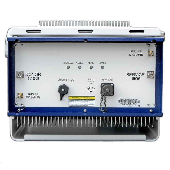
| RF Connector | N-type Female( RF IN_OUT ), SMA Female(coupling port) |
| Coupling port | 20dBc +/- 3dB |
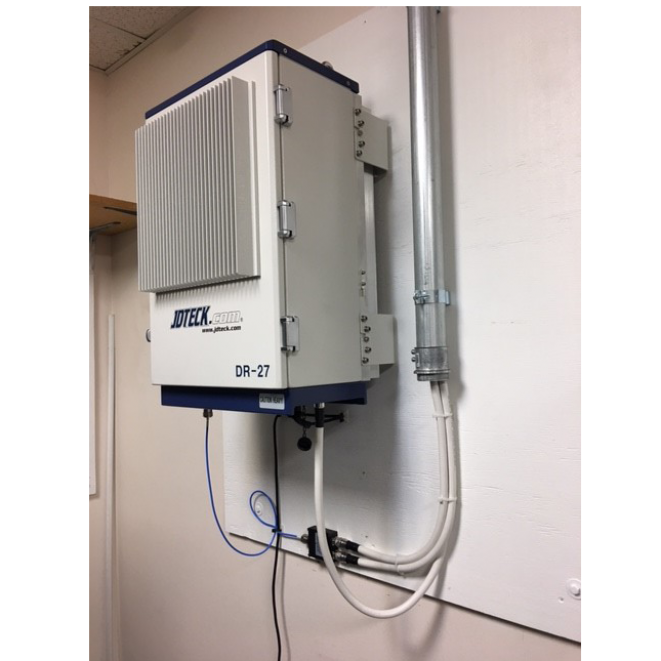
| Environment Condition | Indoor type |
| Ext. Interface | RJ 45 , USB B, SMS Connection |
| Dimensions | 25" x 16" x 14" |
GUARANTEE
This is NOT a CONSUMER device
It is designed for installation by FCC LICENSEES and QUALIFIED INSTALLERS. You MUST have an FCC LICENSE or express consent of an FCC Licensee to operate this device. Unauthorized use may result in significant forfeiture penalties, including penalties in excess of $100,000 for each continuing violation.
Drop File
