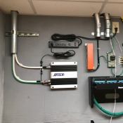
JDCR-LCPA Series (+10dBm)
JDCR-LCPA Series (+10dBm)
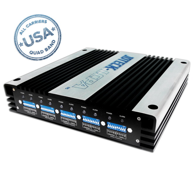
Quad Band Consumer Repeater - USA
Product Overview
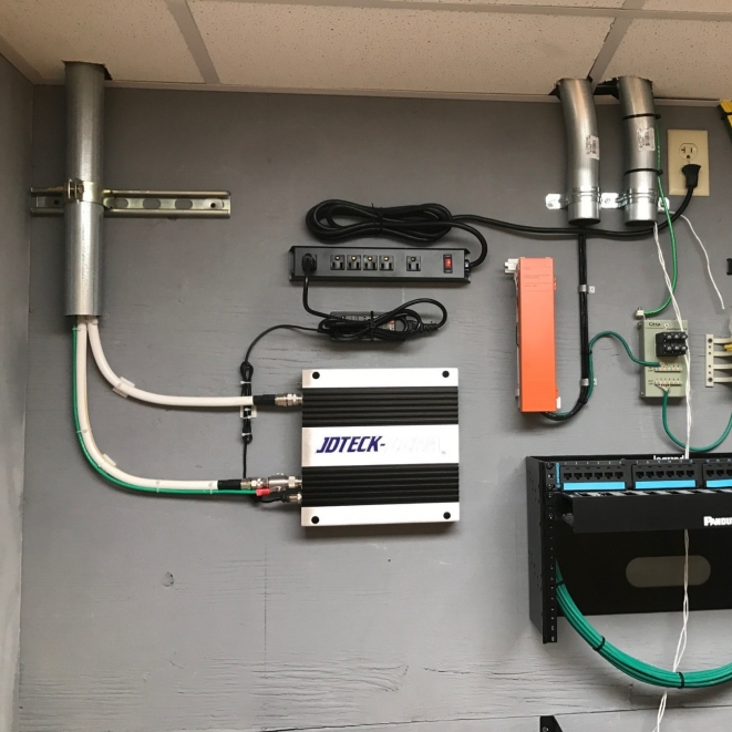
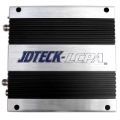
The JDCR- LCPA Series Cellular Repeater is a low-powered, gain adjustable quad band repeater that is perfect for use in a residential DAS application needing to provide enhanced coverage for Voice, 3G and 4G high speed data. Our repeaters are built with carrier level optimization in mind and thus use very high quality internal components to achieve this. These include low noise amplifiers with high linearity, properly specified and set output power limits and well designed alarm/protection circuitry.
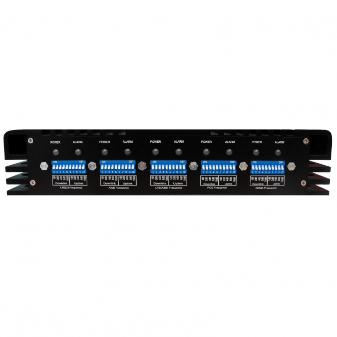
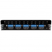
A main feature standard on all our repeaters are individually assigned Uplink and Downlink attenuation adjustment DIP switches. This is particularly advantageous when optimizing your repeater for LTE to ensure you get the best throughput speeds.
A certified test report is included with each repeater that leaves our factory, so you are assured of strict quality controls.
|
|
SKU:
To maintain safe and specific output signal levels, this advanced repeater has built-in AGC (Automatic Gain Control) and ALC (Automatic Limit Control) circuits which can automatically control the gain of the repeater within a 15dB range depending on the RF environmental conditions. In addition, it also has built-in attenuation dip switches that allow you to manually attenuate (fine tune) the repeater's uplink and downlink channels in 1db increments up to 31dB, using color changing LED's as a status indicator. These Alarm LED's are used as a guide to prevent your installation from re-producing errors due to excessive input signal strength if a pre-amp is used, or from signal oscillation due to the indoor antenna and outdoor antenna being too close to each other, which can have adverse effects on a base station and greatly impede system performance.
A Network Safe / MUTE™ feature comes standard with this repeater to protect the cellular network. In short, the repeater will stop transmitting if any errors or signal oscillation is detected within 2-4 sec of detection. It will cycle for 30 sec then attempt to transmit again. If no adjustment in gain has been made to correct the error within the 30 sec MUTE cycle, the system will again shut down after 5 sec. It will run this sequence for a total of 3 times and then shut down completely. Power cycling the unit will reset this sequence.
This repeater is designed to be transparent to the network and will therefore support the same number of calls the serving sector of the BTS the donor antenna is aimed at.
Frequency Chart
| Model | Uplink | Downlink | |
|---|---|---|---|
| JDCR-LCPA-10 | LTE (A&B) | 698 ~ 716 MHz | 728 ~ 746 MHz |
| LTE (C) | 776 ~ 787 MHz | 746 ~ 757 MHz | |
| CELL | 824~849 MHz | 869~894 MHz | |
| PCS | 1850~1910 MHz | 1930~1990 MHz | |
| AWS | 1710-1780 MHz | 2110-2180 MHz | |
| Filter Bandwidth | Wideband | ||
| Max total output power | ≥10dBm | ≥10dBm | |
| Max. Gain | ≥60dB | ≥65dB | |
| Gain Flatness | 700/800/1900: ≤6dB, 1721: ≤8dB | ||
| AGC Range | ≧15dB - Auto shut off after 15dB (MUTE) | ||
| Maximum Input Power | 0dBm | ||
| Gain Control Range (MGC) | ≥31dB in step of 1dB by Dip Switch | ||
| V.S.W.R | ≤3 | ||
| Intermodulation | 9KHz~1GHz≤-20dBm | 9KHz~1GHz≤-20dBm | |
| 1GHz~12.75GHz≤-20dBm | 1GHz~12.75GHz≤-20dBm | ||
| Spurious Emission | 9KHz~1GHz≤-36dBm 1GHz~12.75GHz≤-30dBm |
||
| LTE | Meets 3GPP LTE Standard | ||
| ≤ 12.5% | |||
| ≤ -35dB @ Spreading Factor 256 | |||
| CDMA | ρ > 0.980 | ||
| Meet IS95 & CDMA2000 | |||
| PCS & AWS | Meet 3GPP TS 25.143( V 6.2.0 ) | ||
| ≤ 12.5% | |||
| ≤ -35dB @ Spreading Factor 256 | |||
| Noise Figure (@ max gain) | ≤8dB | ||
| Group Delay | ≤ 1.0μs | ||
| Impedance | 50Ω | ||
| Variable Gain | The UL gain automatically attenuates at the same dB level as the DL gain when the ALC is activated, however the DL gain does not change if UL automatically attenuates. |
||
| Uplink Inactivity | Shuts down after ≥ 295S of the noise level ≥-70dB (LED Flashes OFF & Green) | ||
Mechanical Chart
| Power Supply | Input 90- 264 VAC,50 Hz, transformer: 12V / 11A |
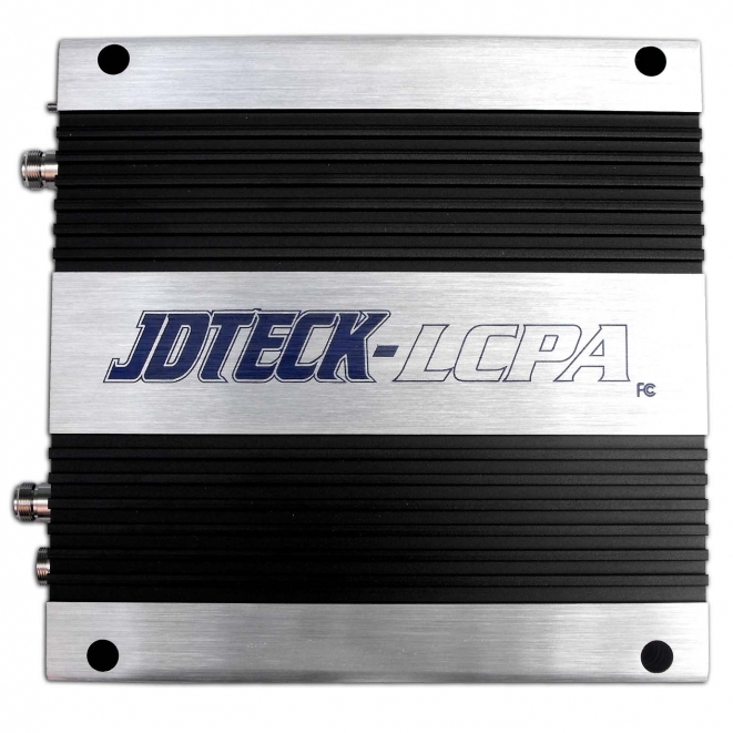
| Cooling | Heatsink Convection Cooling & 3" Brushless Fan |
| Power Consumption | < 35W |
| Operating Temperature | -25°C~+55°C (-13F ~ 131F) |
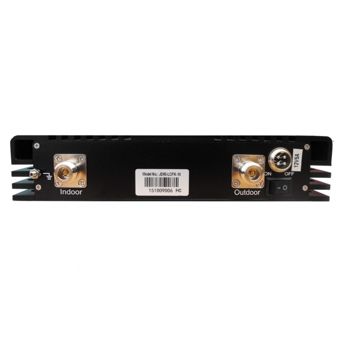
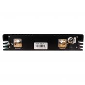
| RF Connector | N Female |
| Weather Proof | IP40 |
| Dimension | 250 x 250 x 52 mm / (9.8" x 9.8" 2") |
| Weight | ≤5Kg (11 Lbs) |
| LED Alarm | Standard |
| Power LED | Power Indicator |
| ALC LED | Amber @ ALC 1~5dB, Red @ ALC 15-20dB |
| LED off after 5 seconds red color |
GUARANTEE
This is a CONSUMER device
BEFORE USE, you
MUST REGISTER THIS DEVICE with your wireless provider and have your provider's consent. Most wireless providers consent to the use of signal boosters. Some providers may not consent to the use of this device on their network. If you are unsure, contact your provider. You
MUST operate this device with approved antennas and cables as specified by the manufacturer. Antennas
MUST be installed at lease 20 cm (8 inches) from any person. You
MUST cease operating this device immediately if requested by the FCC or al incensed wireless service provider.
WARNING. E911 location information may not be provided or may be inaccurate for calls served by using this device.
Drop File
